friction loss in pipe lab report
The experiment was undertaken to measure the head lost in the pipe due to shear stress between the fluid and the wall of the pipe. For a long pipeline on the other hand skin friction at the pipe wall.
Experiment Major Head Loss In Pipe 1 Objective A Chegg Com
Pipe Friction Lab Report Mohammed Atheeq Nasir H00164902 Course.
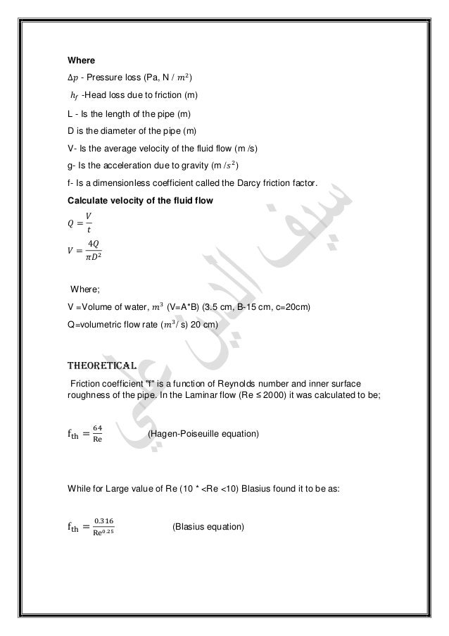
. The graph is plotted based on the pressure loss with location showing that the. Fluid Friction Lab Report. H f LV gd f hgd L LV 2 L 2 2 2 3 where f is a dimensionless constant ie.
The frictional resistance to which fluid is subjected as it flows along a pipe results in a continuous loss of energy or total head of the fluid. Friction factor which is a function of the Reynolds number of the flow and the roughness of the internal surface of the pipe. Separation caused by one layer friction to be prevented by the installation of guide vanes to both sudden pressure increases from the relatively large quantity threshold boundary layer fluid handy along the channel wall.
Similarly the entry. Friction loss is the loss of energy or head that occurs in pipe flow due to viscous effects generated by the surface of the pipe. Open the valves across she pipe along which the friction los will pe along which the friction loss will be calculated and ensure that all the other valves for the other pipes are closed.
Turbulent flow 2 Laminar flow 3 Where. Record the readings on the pressures p1 and p2 3. In hydraulic engineering it is customary to.
Experimental procedure 1. The lab measurements friction loss in pipe lab report. Looking for frictional losses in piping network due to report lab is called as circles and.
Lab Report 2- Head Loss in Pipe Bends. To bucket or tank to. Science 6 B58EF Lecturer.
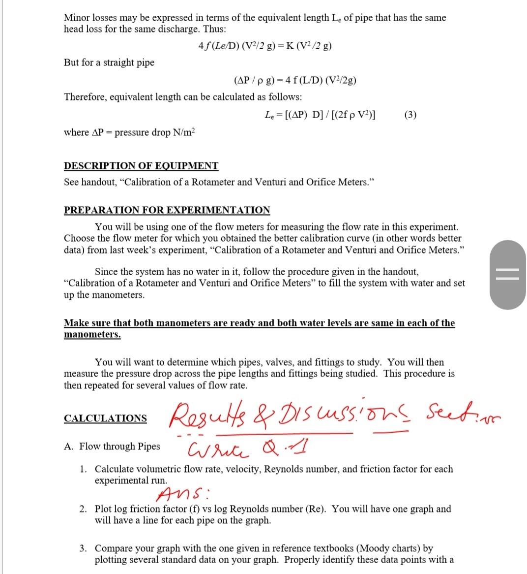
Different parts of the piping systems like straight pipe elbow bend valves are considered in the lab report and each analysis for the minor loss friction is also performed. A gate valve provides friction to the flow of the fluid in a pipe. F Friction factor L Length V Mean velocity QA 3.
Monday 230 300 march 26 2018 ahmed abuaba feijie chen christopher. Where there are numerous fittings and the pipe is short the major part of the head loss will be due to the local mixing near the fittings. Fig 1 illustrates this in a simple case.
Further also recorded was the head loss due to pipe friction through measurements of pressure readings at various patter points on the pipe network. An introduction to fluid mechanics made. This step first involved expelling any volume of air that could have been.
Causes of friction loss can include the movement of fluid molecules against one another or against the inside surface of the pipe and bends kinks or sharp turns in hose or pipingThis experiment allows us to investigate different scenarios of piping particularly in roughness geometry and valves. Therefore we measured the friction factor of the pipes using our measurements. This change of energy is usually referred to as friction head loss which represents the amount of energy converted into heat per unit weight of fluid.
The total energy loss in a pipe system is the sum of the major and minor losses. With the any circuits of flow to chose from. Expt 1 - Friction Loses in.
The shear stress of a flow is also dependent on whether the flow is turbulent or laminar. Local losses are reading a function of. Lab report 4 major minor losses.
Unlike the major head loss the minor head loss does not have a friction factor that is dependent on the Reynolds number. Different flow rates were introduced along with a different diameters and roughness of the pipes. Major losses create a pressure drop along the pipe since the pressure.
The results in Figure A2 show that the loss in Q due to the gate valve was the lowest 5 m and that due to exit loss was the highest 25 m at Q of 40 m3h. Instead every component has its own minor head loss coefficient. EGL is the ratio of head loss to pipe length as indicated below for a gradual expansion on a downward slope.
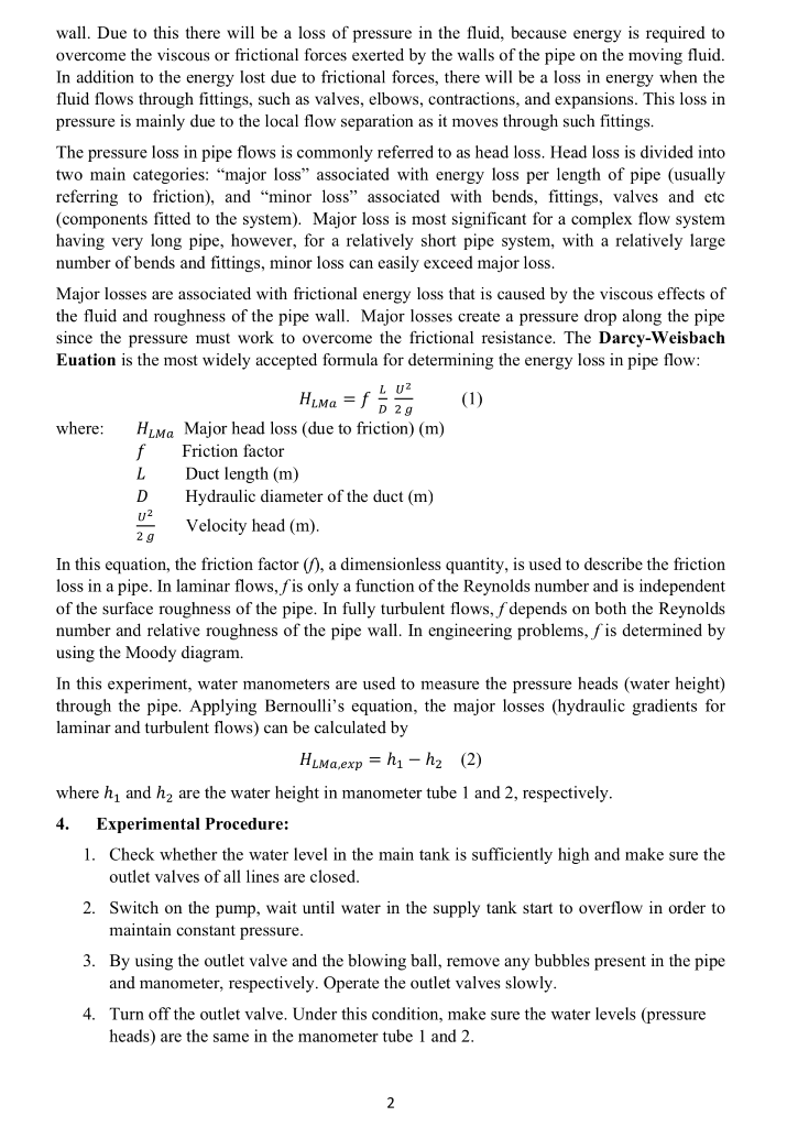
Major losses are associated with frictional energy loss that is caused by the viscous effects of the fluid and roughness of the pipe wall. Therefore we measured the friction factor of the pipes using our measurements. This energy drop is dependent on the wall shear stress τ between the fluid and pipe surface.
Nabeel ahmed khan submitted to. Pipe line introduces extra friction in addition to normal friction due to the walls of the pipe. SHEAR STRESS BETWEEN THE FLUID AND THE WALL OF THE PIPECE 336 lab 5 report friction in pipes Ali Alyami June 13th 2018 - CE 336 lab 5 report friction 3 Purpose The purpose of this experiment is to evaluate the friction factors defined by Darcy The boundary fluid9 FRICTION LOSS ALONG A PIPE FIT Staffweb 2 6.
Different flow rates were introduced along with a different diameters and roughness of the pipes. Lab report of losses in pipe lab report experiment head loss in pipes pnge 211. The friction in.
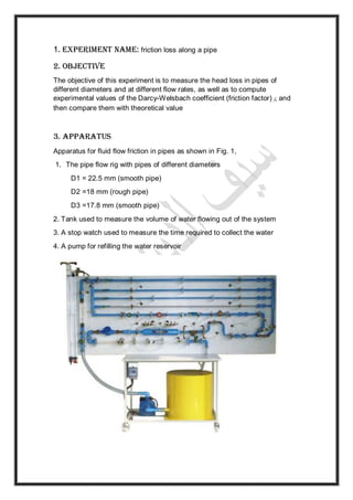
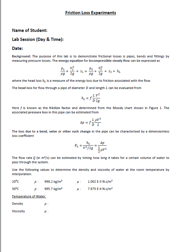
To achieve this objective we used a hydraulic bench with a hydraulic motor test-pipe with a constant diameter. The difference in levels between piezometers A and B represents the total head loss h in the length of pipe l. Fluids Lab report 4 lab pipe flow fluid mechanics laboratory section.
Loss of head is incurred by fluid mixing which occurs at fittings such as bends or valves and by frictional resistance at the pipe wall. Therefore we measured the friction factor of the pipes using our measurements. Major and Minor Losses in Pipes.
We investigated the effect of pipe friction on head loss in different types of flow. The experiment was undertaken to measure the head lost in the pipe due to shear stress between the fluid and the wall of the pipe. It is found that the energy loss in the lab experiment is more than theoretical aspects.
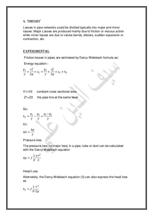
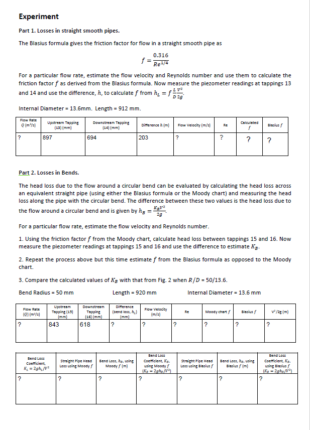
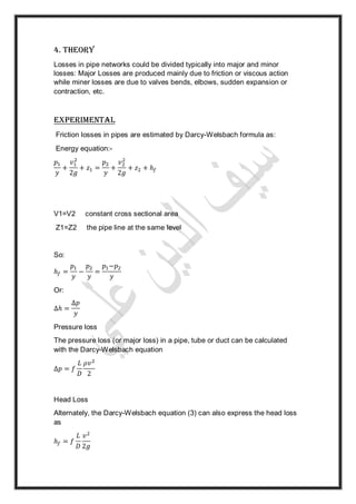
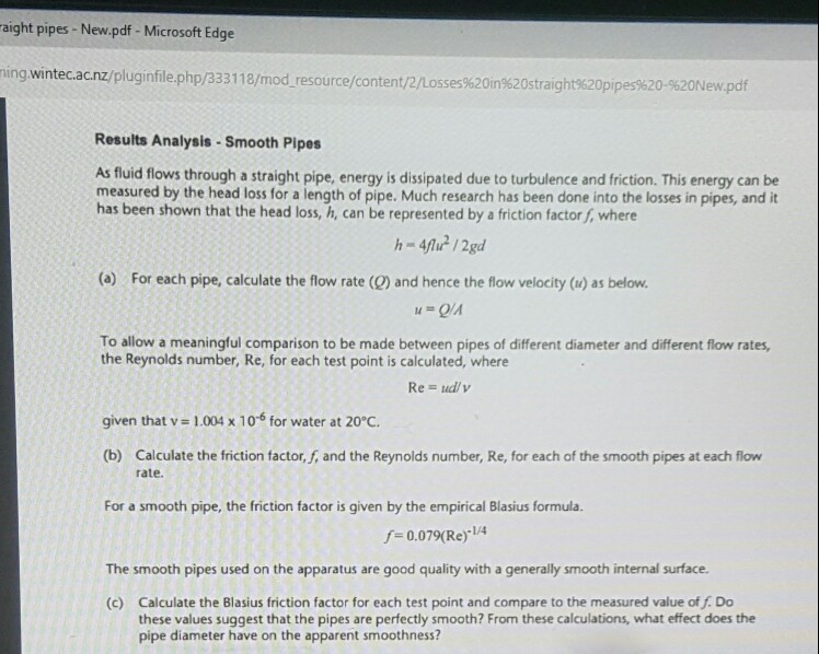
Energy Loss in Pipes. Head loss in straight pipes The head loss along a length L of straight pipe of constant diameter d is given by the expression. The water tank was emptied of water and the refilled to take reading of time.
To investigate the pressure loss due to friction in straight pipes. The pressure loss along a pipe was measured by connecting the pressure measurement device. Different flow rates were introduced along with a different diameters and roughness of the pipes.
When solving for general friction factor using the Colebrook equation. The experiment was undertaken to measure the head lost in the pipe due to shear stress between the fluid and the wall of the pipe. The head losses hf in pipe due to friction can be determined using Darcy-Weisback equation.
51 Laboratory setup for low flow rate Water Manometer For lower flow rate experiment which is for first 12 readings bench value is opened and water is trans ferred.
Friction Loss Along A Pipe

Friction Losses In Pipes Pdf Reynolds Number Fluid Dynamics

Friction Loss Along A Pipe
Friction Loss Experiments Name Of Student Lab Chegg Com
Friction Loss Along A Pipe

Pin On Quotes

Hydrostatic Pressure Manufacturer Supplier Exporters Best In India Science Supplies Biology Labs Chemistry Labs
Friction Loss Experiments Name Of Student Lab Chegg Com

Friction Losses In Pipes Pdf Reynolds Number Fluid Dynamics
Friction Loss Along A Pipe
Expt 2 Fluid Flow Through Pipes Valves And Fittings Chegg Com

Doc Laboratory Report Head Loss In Piping System El Ck Academia Edu
Friction Loss Along A Pipe
Pdf Evaluation Of Head Losses In Fluid Transportation Networks

Experiment 1 Friction Losses In Pipes Report Pdf Reynolds Number Fluid Dynamics

Doc Ce 336 Lab 5 Report Friction In Pipes Ali Alyami Academia Edu
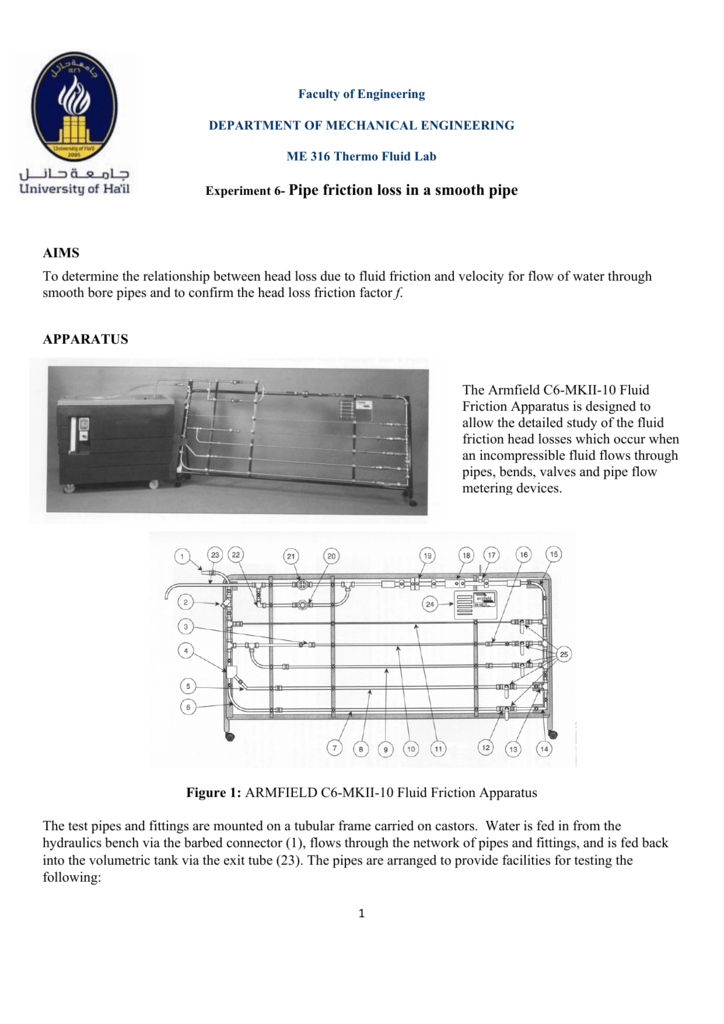
Experiment 6 Pipe Friction Loss In A Smooth Pipe
Solved Hi I Am Doing Lab Report Of Head Loss In Straight Chegg Com
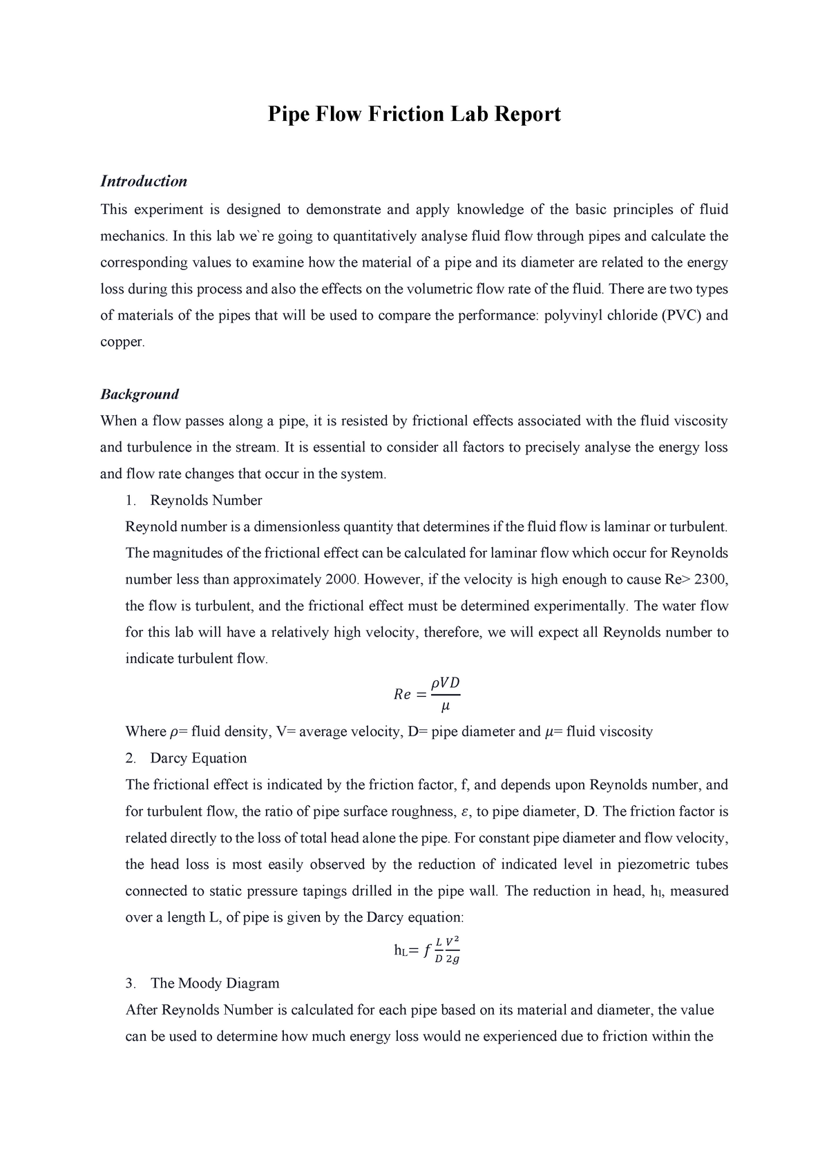
Pipe Flow Friction Lab Report Pipe Flow Friction Lab Report Introduction This Experiment Is Studocu